Phase Diagram
Phase diagram is a plot on temperature and composition space showing the stability of various phase.
In other words, Phase diagram tells us what will be the melting point of alloy.
Phase :-
Physically distinct chemically homogeneous and mechanically separably state of any matter is called phase.
Degree of Freedom :-
Number of independent variable requires to define the state of any matter is called Degree of Freedom(DOF).
Mixture of different phase will be in equation only when it follows Gibbs phase rule.
P + F = C + 2
Where,
P – Number of Phases
F – Degree of Freedom
C – Number of Component
- C=1 – Unary phase diagram
- C=2 – Binary phase diagram
- C=3 – Ternary phase diagram
TYPES OF PHASE DIAGRAM
1. Binary Phase Diagram :-
Materials which are completely soluble both in liquid and solid state.
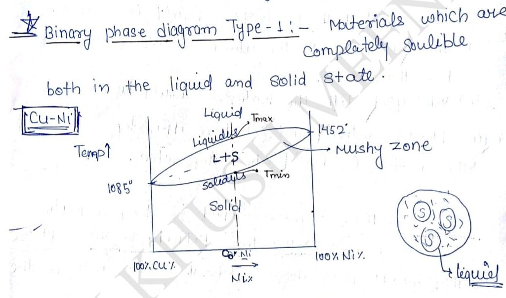
Cu and Ni both combines together and produces a single phase in solid state, it is called Solid Solubility. Au the lines appearing on the phase diagram are the properties of alloy and can not be changed. There appear a region on such phase diagram where there is a mixture of liquid and solid called Mushy zone.
Layer is the extent of mushy zone more will be the variation in properties of that alloy. Any line on the phase diagram that separate the mushy zone with liquid phase is called liquidus. Any line on the phase diagram that separate mushy zone with solid phase is called solidus as it can seen in the diagram that if mushy zone is appear in the alloy melting point will not be fixed there will a range of temperature at which liquidification and solidification takes place.
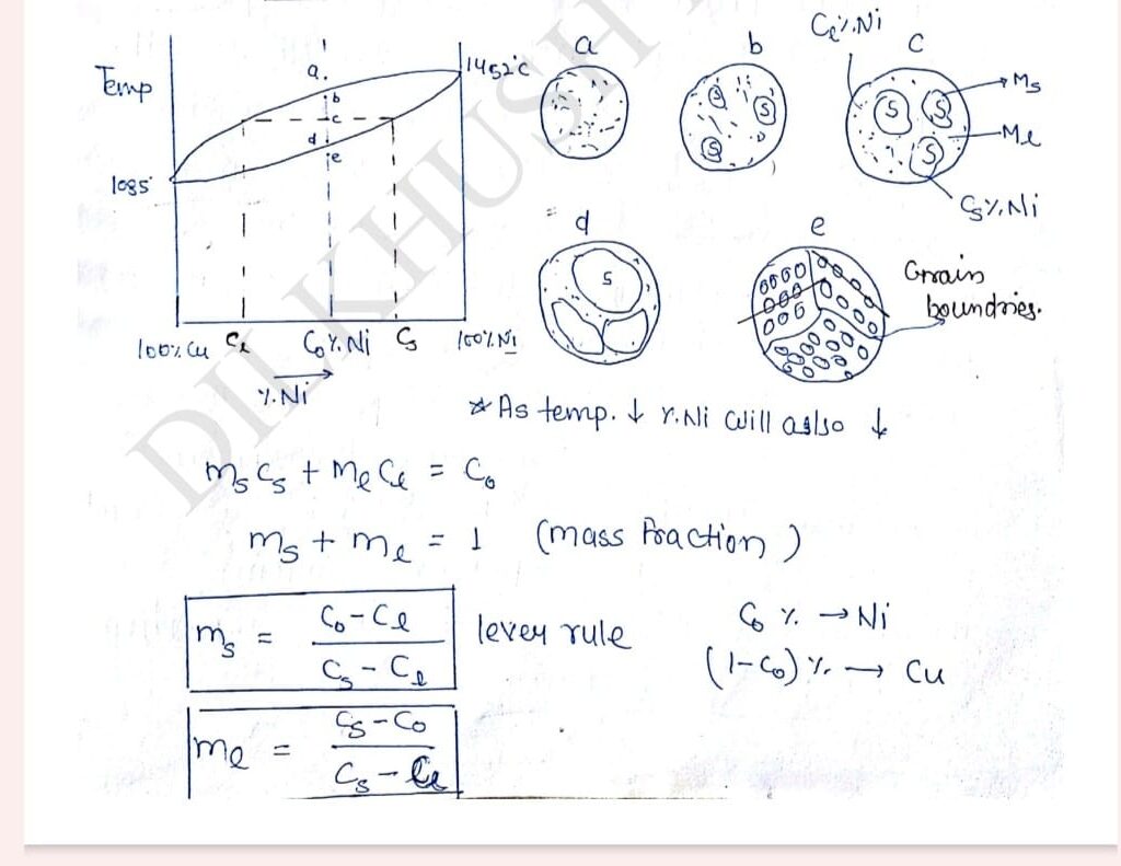
Lever Rule can only be in a Two Phase Region.
A sample of Cu-Ni with Co% Ni is cooled along line a-b slowly point ‘a’ is above the liquids line so entire microstructure in the liquid phase the moment temp. of sample slowly decreases to point ‘b’ solid start nucleating in microstructure at thousands of places up on the decreasing the temperature from point ‘b’ to ‘d’ following conclusion can be drawn be using lever rule:
1. As the temperature decreases mass fraction of solid phase keeps on increasing.
2. The moment solid nucleated % of Ni in the solid is quite high upon decreasing the temperature, % of Ni in solid keeps on decreasing at approach towards the overall composition Co.
3.At high temperature phenomena called diffusion appear in the solid which tries to humongous the composite. It is solid the every 20 degree celsius increase in temperature diffusion multiply by 2(2xdiffusion). So, Ni will diffuse from center to outward direction and make composition uniform throught. So, within the solid phase composition of Cu and Ni will uniform.
Each and every solidification form will have a particular arrangement of atom. The moment temperature of the sample slightly decreases below the solidus line different solidification fronts will fuse together and entire microstructure will convert into solid phase. The regions where different solidification fronts are melting there will be mismatch in the orientation of atom. These region of orientation mismatch are called Grain Boundaries.
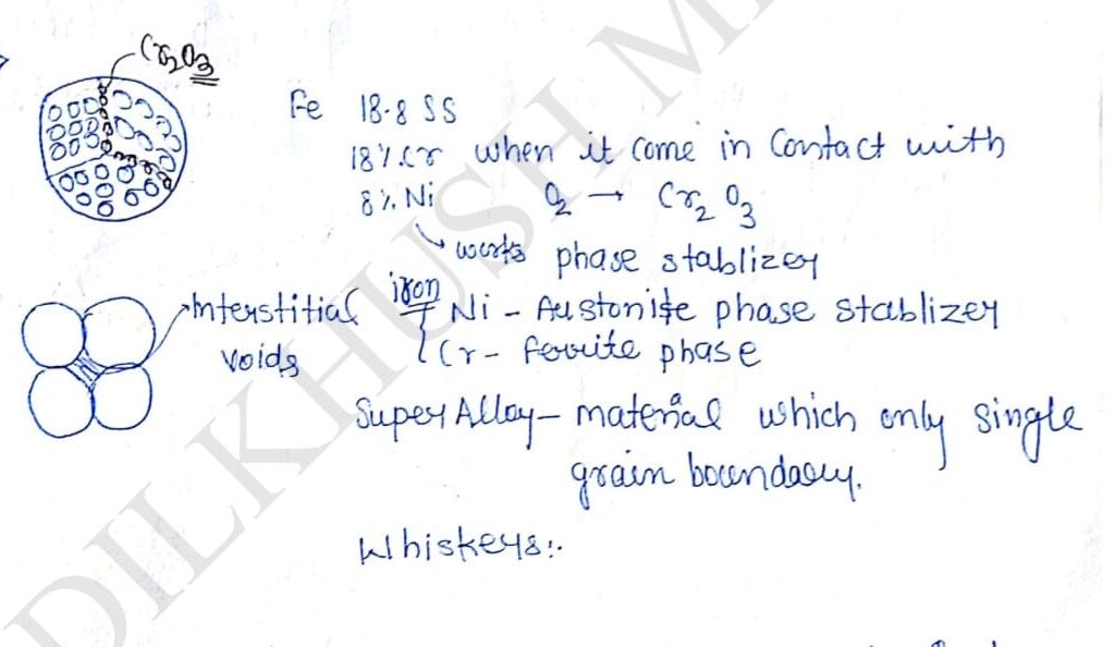
At the grain boundary since bond length is large so easily bond can break so atmospheric oxygen first attach the grain boundary and corrosion it, that’s why it is solid that grain boundaries at are high energy level.
To increase corrosion resistance of any material is added in it Cr after reacting with oxygen produces Cr2O3 (chromium oxide ) and it get accumulate grain boundary protecting the grain boundary from the attach of other gases.
1.Ni is a phase stablizer in case of iron Ni is austenite phase stablizer and Cr is ferrite phase stablizer.
2.To protect any material from grain boundary corrosion either foreign phase accumulate at grain boundary or the grain boundaries should completely remove from material.
3.The material where their is no grain boundaries are called super alloy. Super alloys in thin section are called Whiskeys.
Fe-C Phase Diagram/Iron-Cementite(Fe3C) Phase Diagram :-
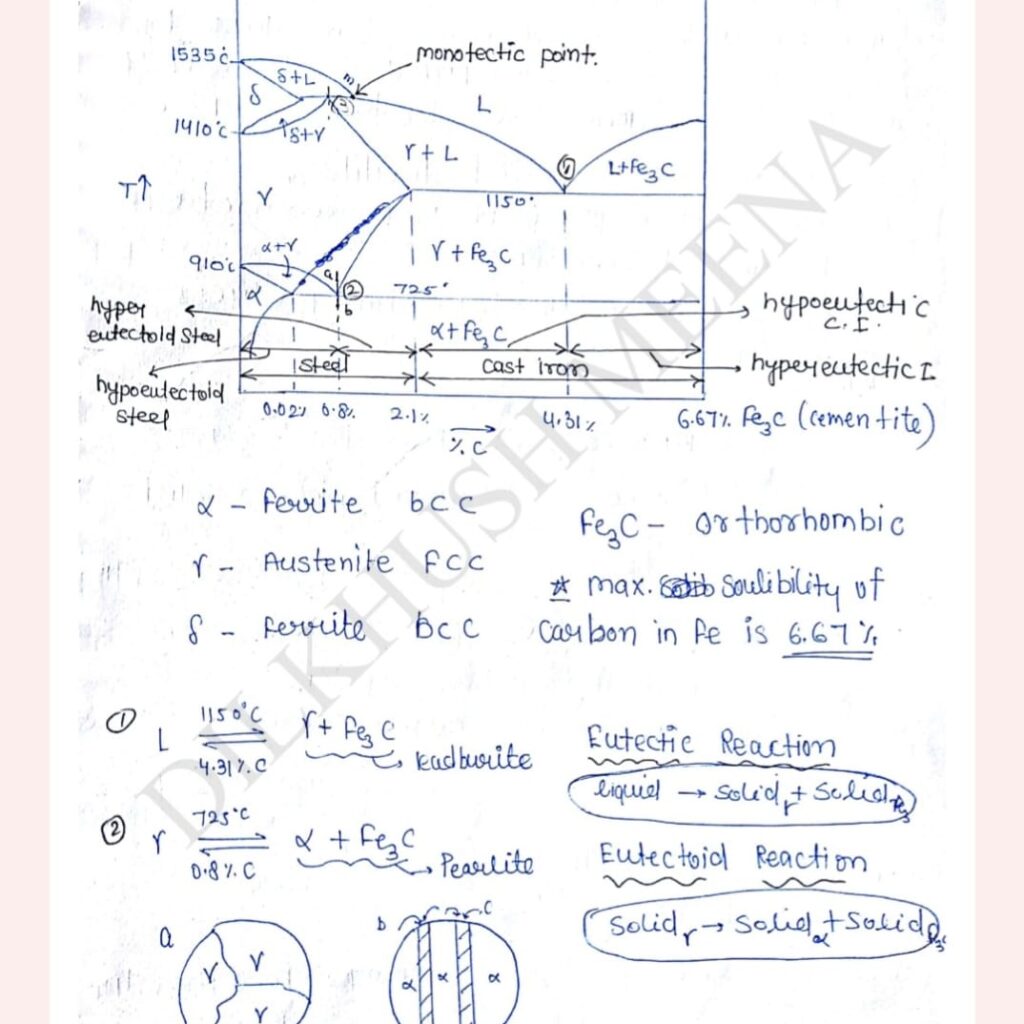
At 0.8% at 726 degree celsius carbon is uniformly distributed in the microstructure. When the temperature of sample slowly decreases below the eutectoid temperature since austenite can not present in stable form. So carbon from one interstitial site to another and produces alternate like structure (alpha+Fe3C) this microstructure is called Pearlite.
Similarly, Eutectic decomposition on produces Ledeburite
Gray Cast Iron
In pure iron carbon system when more then 6.67% C is addeol, a portion of a C come out on the microstructure and appear on Free or flap form. Such cast irons are called Gray Cast iron. These material are used to manufacture machine bed because Graphite pockets act like Vibration damper and hence absorbs vibration.
White Cast Iron
Very hard and brittle. When a % of 0 is less than 6.67% antire amount. of carbon will appear in combined form and these material are called white cast iron.
Chilled Cast Iron
Cast iron of such composition in which normally it will Frage as gray but forced to appear as void by rapid cooling is called Chilled cast Iron both white and chilled cast iron are brittle in nature. So these material are not use directly in any engineering application. These material are used to make ductile Cast Irom.
Spheroidal Gray Cast Iron
If the objective to produce ductile cast iron small amount of Mg, Ce (Cerium) is added in the material. These material act like catalyst in the diffusion process of carbon after producing chilled Cast iron the material again heat to a temp <1150°C and than cooled extremely slowly in the furnace at thousand of places carbon will diffuse at the center and produces spheroid. This increase the overall ductility of material if the cooling rate are slightly faster Combined form of carbon appear in the middle like form is called Nodular Cast iron.
Effect of Sulphur (s) and Magnise (Mn)
Whatever liquid & solid present in nature Impurity of Sulpher cannot be avoided so Sulpher will present in iron also. Impurity of Sulphur in iron is very dangerous because after reacting with iron it produces iron Sulphide (fes) and it get accumulated at grain boundaries.
Melting point of Fes is very low so upon warm forming of the material, Fes will melt out producing & Cracks at grains boundaries thats lead to brittle fracture this phenomena called hot shortness of Sulphur – embrittlement.
To avoid the ill effect of Sulphur small amount of manganese (Mn) is added in material. Mn capture manganese Sulphur before Sulphur capture iron, and produce manganese sulphide (Mns).
Melting point of Mns is quite high so hot- Shortness phenomena will be gone. Shear strength of Mns is low and this increases the machinability of material. Further addition of Mn increase strength of material, and with 12%, Mn Material become exceptionally become very strong Hadfield steel used in heavy duty applications like bulldozer.
To produce steel carbon has to removed from material so O2 is injected in liquid Iron pond 02 after reacting with carbon present in liquid iron produces CO2. So carbon is remove from maternal by converting into gas since it is exothermic reaction liquid iron pond appears to boil and this phenomena is called steel boil. When we stop the flow of o₂ there will be a tendency in steel to capture a portion of oxygen (02) .Silicon is added in the liquid metal to remove this trapped oxygen. When oxygen is completely removed from material it is called skilled steel and when removal of oxygen is partial is called semi-skilled steel.
Fyyobe? Okay, I’ve given it a whirl. Lots of game choices, which is awesome. Needs a little polish in the customer service department, just saying. Give it a look: fyyobe
Panalobet’s kinda new to me, but the bonuses are making me stick around. Could use a few more games, but can’t complain so far. Give panalobet a try and see what you think!
Alright, time to dive into x555com! Hope to find some awesome games. Login process seems easy enough. Lets gooo: x555com
Heard some buzz about 0066betlogin. Let’s see what it’s all about. Hoping for a quick login so I can get right to betting! Good luck to me: 0066betlogin
Just signed up on 666p. Seems interesting! Login was quick. Will let you guys know if I got some good stuff inside! Here’s the link if you wanna try 666p
Yo, lemme tell ya about cz777gamelogin. Signed up real quick and was playing in minutes. The site’s clean and the games are hella fun. Seriously, give it a whirl! Login and level up: cz777gamelogin
Ganabetsportium? Never heard of it before, but I’m always up for trying something new. Here’s hoping for a great sportsbook and easy betting! ganabetsportium
Alright, checking out alanobet999. The name’s got a nice ring to it. Let’s see if the games are as good as the name. Fingers crossed for a winning streak! alanobet999